System and Method for Non-Intrusive Detection of Pressure Tank Degradation and Differential Diagnosis of Short-Cycling Faults in Residential Well Pump Systems
Abstract
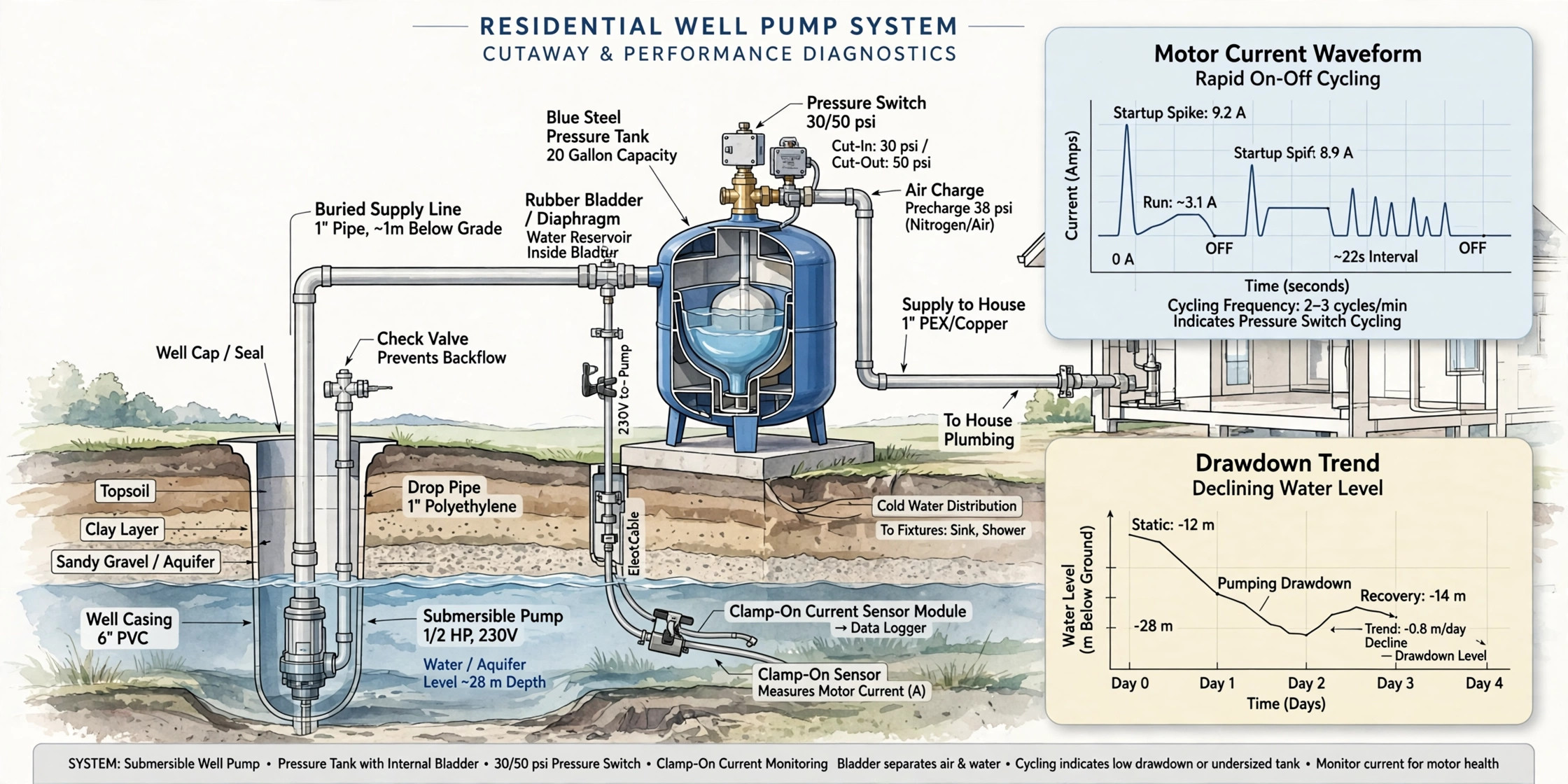
Disclosed is a non-intrusive system and method for detecting pressure tank degradation and diagnosing the root cause of short-cycling in residential well pump systems before the pump is destroyed. A current sensor clamped on the well pump branch circuit, requiring no plumbing or wiring changes, samples pump motor current and extracts each cycle's run time from cut-in to cut-out, off time between cycles, inrush transient, and running current. From these electrical features the system computes effective tank drawdown per cycle and tracks its decay against a learned baseline, producing a Tank Health Index that falls monotonically as the bladder or diaphragm degrades. A differential-diagnosis engine separates six failure modes from the same electrical signature: bladder degradation, system leaks, pump wear, low well yield, pressure-switch chatter, and incorrect air charge. Escalating alerts are tied to the industry one-minute minimum pump run-time rule, and a sudden step change in drawdown flags bladder rupture. The system thereby catches the most common pump-killing fault, a waterlogged tank, weeks before the pump motor fails from exhaustion.
Field of the Invention
This invention relates to residential water well systems, specifically to non-intrusive condition monitoring of pressure tanks and well pumps through electrical signature analysis of pump motor current and cycle-timing analytics, enabling predictive detection of tank degradation and automated root-cause diagnosis of short-cycling faults.
Background
Millions of American households draw water from private wells, and the pressure tank sitting beside most of them decides how long the pump lives. The tank holds a cushion of compressed air above a rubber bladder or diaphragm full of water. When the pump runs, it fills the bladder and compresses the air; when a tap opens, the compressed air pushes water out without the pump running. This stored volume between cut-in and cut-out pressure, the drawdown, is what keeps the pump from starting every time someone washes their hands.
When the bladder ruptures or the air charge bleeds away, the tank waterlogs. Without the air cushion there is no drawdown: opening a faucet drops pressure instantly, the pump starts, closing the faucet lets pressure rise instantly, the pump stops. The result is rapid cycling measured in seconds. Well service professionals report that a waterlogged tank accounts for roughly 70% of short-cycling cases (SCWS), and that a pump which should last 15 to 20 years can fail in 3 to 5 years under severe short cycling (SCWS). As one tank supplier puts it, most well pumps that get replaced did not need replacing: the tank next to them failed, the pump started and stopped every few seconds trying to compensate, and the motor died of exhaustion (Ken's Distributing).
The economics make early detection valuable. A submersible pump replacement runs $1,500 to $4,000 installed (Plumbing Supply and More), while the tank that kills it costs $700 to $1,050 to replace (answersbyexpert). Pressure tanks themselves last only 7 to 12 years (Engineer Fix), and pump manufacturers will not honor a warranty when the failure is tied to a waterlogged tank (H2O Equipment). The industry sizes tanks for a minimum of one minute of pump run time per cycle (Ken's Distributing), and bladder tanks require an air pre-charge set 2 psi below the pressure switch cut-in, measured with the tank drained (gritandhome).
Current practice detects all of this late and manually. A homeowner notices pressure surging at the fixtures, calls a contractor, and the contractor kills power, drains the tank, presses the Schrader valve, and checks whether water squirts out instead of air, the classic ruptured-bladder test (Engineer Fix). By then the pump has often endured months of destructive cycling. Existing monitors, where they exist at all, are pressure gauges read by humans or simple run-time alarms that cannot say why the pump is cycling.
Non-obviousness. No reference teaches diagnosing well system faults from the pump's electrical signature alone, without any pressure measurement. The manual art teaches draining the tank and checking pre-charge with a gauge, a procedure that only works after failure is already suspected, and teaches away from electrical monitoring entirely. The claimed insight is that the pattern of cycle-timing compression discriminates root causes: bladder degradation compresses run time and off time proportionally while cut-in and cut-out pressures stay fixed, a system leak shortens off time while run time stays constant, a failing pump extends run time and raises running current, and switch chatter produces sub-second micro-cycles. None of these signatures requires a pressure transducer; they emerge from the current envelope once the system's normal drawdown is learned. The further insight that drawdown decay can be trended to predict bladder rupture weeks in advance, rather than detected after the tank is already waterlogged, appears nowhere in the cited art.
Detailed Description
1. Non-Intrusive Sensing Hardware
The preferred embodiment is a split-core current transformer clamped on the well pump branch circuit conductor inside the service panel or at the pressure-switch wiring, powered by a USB supply and requiring no modification of the pump, tank, or plumbing. It contains: a current transformer with 0.1 to 30 A range covering fractional to multi-horsepower pumps at 120 or 240 VAC; a microcontroller sampling the current waveform at 1 kHz or faster; an energy metering front end reporting true RMS current and active power; and a WiFi radio transmitting per-cycle feature vectors, not raw waveforms, to a home hub or cloud service. Target bill-of-materials cost: $30 to $50.
An alternative embodiment integrates the metering circuit into the pressure-switch enclosure at manufacture. A further embodiment adds a pressure transducer threaded into the tank tee's gauge port for direct pressure measurement; this is optional, and the diagnostic engine is designed to operate fully without it.
2. Cycle Extraction from the Current Envelope
The microcontroller runs a state machine on the RMS current envelope. Idle is declared below 0.2 A. A cycle begins at cut-in: current rises from idle through an inrush transient, typically 3 to 7 times running current for 100 to 300 ms in a submersible induction motor, then settles to the running plateau. The pump runs until the pressure switch opens at cut-out, when current falls back to idle. Run time T_on is the interval from inrush start to cut-out; off time T_off is the interval from cut-out to the next inrush. Each inrush increments a starts counter, from which starts per day and starts per hour are derived.
Partial or interrupted cycles, such as a pump stopped mid-cycle by a breaker trip or power outage, are flagged and excluded from drawdown trending but retained for the starts counter, since every start still stresses the motor.
3. Effective Drawdown Estimation and Baseline Calibration
Effective drawdown per cycle is estimated from T_on and the pump's flow rate at the operating pressure band. The pump's rated flow is supplied at installation (from the pump label or installer input) or learned: during the calibration period the system observes T_on across cycles at known usage and fits the flow that makes drawdown estimates consistent with the tank's nameplate drawdown at the configured pressure switch settings. A 30-day calibration period capturing at least 60 full cycles establishes baseline drawdown D0, baseline T_on0, and baseline T_off0 at each hour of the day, since household usage patterns modulate off time.
With the optional pressure transducer, drawdown is measured directly from the pressure trace: the volume delivered between cut-in and cut-out is read from the tank's drawdown curve at the measured pressures, and the air pre-charge is verified against the 2 psi-below-cut-in rule, prompting a recharge check when violated.
4. Tank Health Index and Trend Projection
The Tank Health Index H is initialized to 1.0 after calibration and computed as the ratio of current median effective drawdown to baseline drawdown, passed through an exponentially weighted moving average with a time constant of 14 days to suppress usage-pattern noise:
H = EWMA(median(D_cycle) / D0)
H falls monotonically as the bladder loses air charge or develops pinholes. A linear fit to H over a trailing 60-day window projects the date at which H crosses the 0.5 service threshold, giving weeks of advance notice. A step drop in H exceeding 25% between consecutive 7-day windows, with no change in usage pattern, is classified as bladder rupture: the air cushion did not decay, it vanished.
5. Differential Diagnosis Engine
The same cycle features feed a rule-based classifier that distinguishes six fault modes, because the correct fix differs completely between them and misdiagnosis wastes a service call:
- Bladder degradation / waterlogging: T_on and T_off compress proportionally, drawdown decays monotonically over weeks to months, running current and cut-in/cut-out behavior unchanged. Fix: recharge air or replace tank.
- System leak (toilet, irrigation, pipe): T_off shortens while T_on stays at baseline; drawdown per cycle constant; pump reaches cut-out normally. Total daily run time rises without any change in per-cycle timing. Fix: find the leak, not the tank.
- Pump wear (impeller, worn bearings): T_on extends progressively, running current drifts upward from baseline, cut-out is reached late or the pump stalls below cut-out. Fix: service or replace the pump.
- Low well yield / dry running: T_on extends with pressure stalling below cut-out and running current deviating from the learned baseline as the pump ingests air; cycles cluster during high-demand periods. Fix: well yield test, lower the pump, or add storage.
- Pressure-switch chatter: micro-cycles with T_on or T_off below 2 seconds, often in bursts, with contact-bounce current signatures. Fix: replace the switch and check the sensing nipple for clogging.
- Incorrect air charge from installation: drawdown reduced from the first day of monitoring with no decay trend; H starts below 0.8 and stays flat. Fix: drain tank and set pre-charge to 2 psi below cut-in.
The classifier requires no pressure sensor for any of these distinctions. The proportional-compression signature of tank degradation versus the off-time-only signature of a leak is the key discriminator, and it is visible purely in the electrical cycle timing once the baseline is learned.
6. Alert Thresholds and the One-Minute Rule
Alerts are anchored to the industry minimum of one minute of pump run time per cycle. The system issues: an informational notice when median T_on falls below 90 seconds, approaching the sizing rule; a service-scheduling alert when median T_on falls below 60 seconds, the point at which the installation is effectively undersized by degradation; and a critical alert when median T_on falls below 30 seconds or starts per day exceed a configurable budget (default 100), the regime in which pump life collapses from 15-20 years toward 3-5 years. Bladder-rupture step detection triggers an immediate alert regardless of thresholds, since a ruptured bladder waterlogs the tank within days.
A starts-per-day budget counter projects motor start-life consumption: each start's inrush is the dominant thermal and mechanical stress event for the motor, so the system reports starts per day against the budget and estimates remaining start-life from the manufacturer's rated starts, where published, or a default 300,000-start reference for residential submersibles.
7. Fleet Learning
Deployed units contribute anonymized drawdown-decay curves keyed by tank model, tank age, pressure-switch settings, and pump type. The fleet model refines the decay-slope priors that drive the rupture projection, and learns which tank models waterlog fastest, without transmitting any identifiable household data.
8. Figures Description
- Figure 1: Current envelope traces for three pump cycles at three tank health states: healthy (long T_on, long T_off), degraded (compressed proportionally), and ruptured (seconds-long cycles).
- Figure 2: System block diagram showing the clamp-on current sensor at the panel, the feature extraction pipeline, the drawdown estimator, the Tank Health Index trend engine, the differential-diagnosis classifier, and the alert hub; optional pressure transducer shown dashed.
- Figure 3: Example Tank Health Index trend over 18 months showing gradual bladder decay, the 90/60/30-second equivalent thresholds, the linear projection to the service threshold, and a rupture step event.
- Figure 4: Decision tree of the differential-diagnosis engine mapping observed cycle-timing signatures to the six fault modes.
Claims
- A system for detecting pressure tank degradation in a residential well pump installation, comprising: a non-intrusive current sensor electrically coupled to the well pump branch circuit without modification of the pump, tank, or plumbing; wherein the sensor samples pump motor current waveform at 1 kHz or faster, extracts per-cycle run time from cut-in to cut-out, off time between cycles, inrush transient magnitude, and running current, estimates effective tank drawdown per cycle from run time and pump flow rate, and computes a tank health index from the trend of effective drawdown against a learned baseline.
- The system of claim 1, wherein cycle boundaries are detected from an RMS current envelope state machine that identifies the inrush transient at cut-in and the current collapse at cut-out, and wherein interrupted cycles are excluded from drawdown trending while retained in a motor starts counter.
- The system of claim 1, further comprising a differential-diagnosis engine that classifies, from cycle-timing features alone and without any pressure measurement: bladder degradation by proportional compression of run time and off time with monotonic drawdown decay; system leak by shortened off time with constant run time and constant drawdown per cycle; pump wear by extended run time with upward drift in running current; low well yield by extended run time with pressure stall and baseline-deviating running current; pressure-switch chatter by micro-cycles below 2 seconds; and incorrect air charge by reduced drawdown from installation with no decay trend.
- The system of claim 1, further comprising a bladder-rupture detector that identifies a step drop exceeding 25% in the tank health index between consecutive 7-day windows with no change in usage pattern, and in response issues an immediate rupture alert.
- The system of claim 1, further comprising an alerting module that issues escalating alerts when median pump run time falls below 90 seconds, below 60 seconds, and below 30 seconds, anchored to the industry minimum one-minute pump run-time sizing rule, and when starts per day exceed a configurable budget.
- The system of claim 1, further comprising a starts-per-day budget counter that tracks motor start events from inrush transients, reports starts per day against a configurable budget, and projects remaining motor start-life.
- The system of claim 1, further comprising an optional pressure transducer at the tank tee that directly measures cut-in and cut-out pressures, verifies air pre-charge against the 2 psi-below-cut-in rule, and refines drawdown estimates.
- The system of claim 1, wherein only per-cycle feature vectors are transmitted off the sensing device, with raw current waveforms processed locally and discarded.
- A method for non-intrusive diagnosis of short-cycling faults in residential well pump systems comprising: non-intrusively measuring well pump motor current at 1 kHz or faster from the pump branch circuit; segmenting operation into cycles using an RMS current envelope state machine that detects inrush at cut-in and current collapse at cut-out; estimating effective tank drawdown per cycle from run time and pump flow rate; trending the drawdown against a learned baseline to compute a tank health index; and classifying the fault mode from the pattern of run-time and off-time compression without pressure measurement, distinguishing bladder degradation, system leak, pump wear, low well yield, switch chatter, and incorrect air charge.
- The method of claim 9, further comprising projecting a service date by linear extrapolation of the tank health index trend to a 0.5 threshold, and detecting bladder rupture from a step drop exceeding 25% between consecutive weekly windows.
Implementation Notes
Baseline quality determines diagnostic accuracy. The 30-day calibration period should capture at least 60 full cycles; vacation homes and seasonal cabins with sparse cycling should extend calibration to 90 days. The learned baseline absorbs installer-specific factors such as pressure-switch settings, tank model, and pump curve, so a baseline must be re-learned after any professional service event, detected automatically by a step change in drawdown followed by a stable new plateau.
Air-over-water (non-bladder) tanks are supported: their drawdown decays gradually through air absorption rather than rupturing, so the rupture step detector is desensitized and the projection model uses a slower decay prior. Constant-pressure systems using variable-frequency drives are an alternative embodiment in which cycle timing is replaced by drive-speed and run-time analytics, since the drive eliminates discrete cycles; the differential-diagnosis signatures transfer with speed replacing run time.
The same method extends to booster pump systems with hydropneumatic tanks in homes on municipal water with low pressure, where the identical short-cycling failure mode destroys booster pumps. No claim is made on the tank replacement or air-recharge procedure itself; this disclosure covers detection and diagnosis only.
Prior Art References
- SCWS : Well Pump Cycles On and Off Frequently : Waterlogged tank causes roughly 70% of short cycling; pump life 15-20 years collapses to 3-5 years under severe cycling
- Ken's Distributing : Well Pressure Tank Guide : Most replaced pumps did not need replacing, the failed tank killed them; size for one minute of pump run time minimum; air charge 2 psi below cut-in
- Plumbing Supply and More : Submersible Well Pump Costs : Submersible replacement $1,500-$4,000 installed; pump life 15-20 years
- Engineer Fix : How to Fix a Waterlogged Pressure Tank : Pressure tank lifespan 7-12 years; Schrader valve water test indicates ruptured bladder
- gritandhome : Well Pressure Tank Waterlogged or Pump Short Cycling? : Diagnostic pressure readings; pre-charge rule of 2 psi below cut-in with tank drained
- answersbyexpert : A Waterlogged Pressure Tank Short-Cycles the Well Pump : Tank replacement $700-$1,050; diagnostic specifics for contractor quotes
- H2O Equipment : Water Logged Pressure Tank : Pump warranty void when failure is tied to a waterlogged tank; waterlogging blocks water treatment regeneration